SpyScanmultimodal hidden-camera detection
One portable device that collects several independent kinds of physical evidence and combines them, so it can find the cameras that a single sensor misses.
- Role
- Sole developer
- Context
- Embedded Systems project, ITMO
- V1 platform
- ESP32-S3, ESP-IDF, FreeRTOS
- Source
- simu18/SpyScan
Detectors that only say “something is here”
Tiny cameras are cheap and easy to hide in rented rooms, hotels and changing rooms. Affordable detectors use one trick. RF detectors beep at any transmitter, including the router and every phone in the room. Lens finders make the user stare through a red filter and judge glints by eye. Neither gives evidence that is specific to a camera, and a camera that records to an SD card and transmits nothing defeats the RF approach completely.
Every camera type fails at least one test
A Wi-Fi camera can hide its lens but not its traffic. An SD-card camera transmits nothing but still has a lens and still runs a video encoder. So instead of trusting one sensor, SpyScan treats each method as a separate line of evidence and combines them. The full system is planned in six stages:
- V1Optical retroreflection and Wi-Fi traffic analysisFind lenses by the light they return, and find streaming cameras by how their traffic responds to a known stimulus.
- V2Automatic optical classificationMulti-angle LEDs and image features to tell a lens from screws, glass and glints.
- V3Wideband RF with software-defined radioSpectrum analysis beyond Wi-Fi and Bluetooth, plus direction finding with a directional antenna.
- V4Offline cameras through electromagnetic side channelsA camera recording to an SD card still encodes video. Flash a known light pattern and look for an electromagnetic emission that follows it.
- V5Thermal sensingA thermal array as supporting evidence for powered electronics.
- V6Sensor fusion and camera-type estimateCombine every channel into one confidence score, and say whether the likely camera is wireless or recording locally.
- RResearch: non-linear junction detectionDetecting electronics that are switched off. A research project of its own, not planned for the device.
Only V1 is being built now. Everything after it is a plan, labelled that way on purpose.
Ask the scene a question and see who answers
The most important technique in the project is challenge and response. A camera reacts to what it sees: when the scene changes, its video encoder works harder and its output changes. So SpyScan changes the scene on purpose, with a pseudo-random light or motion pattern, and tests which signal follows that exact pattern. Random electronics will not match a sequence they have never seen.
In V1 the signal is Wi-Fi traffic. In V4 the same test runs on electromagnetic emissions, which is how an offline camera could be caught. V1 is where the method is tested before the hard case depends on it, and the first real cameras already showed where it breaks: an encoder with a constant bit rate does not answer at all. Drag the slider to zero to see that case.
Why twelve slots: with a balanced pattern of K slots the smallest possible p is 1/C(K, K/2). Twelve slots give 1/924, enough to reach p < 0.01; eight would not.
V1: two methods, one handheld device
Optical. A red LED ring sits around the camera. The device takes frames with the LEDs on and off and subtracts them, which cancels lamps and daylight and leaves only light reflected straight back, the cat's-eye effect of a lens. A second LED pair, offset by at least 30 mm, separates real lenses from glints.
Wireless. The ESP32-S3 listens in promiscuous mode and logs every transmitter's uplink and downlink bytes, frames and signal strength in 100 ms bins. That feeds both the challenge test and a passive streaming signature.
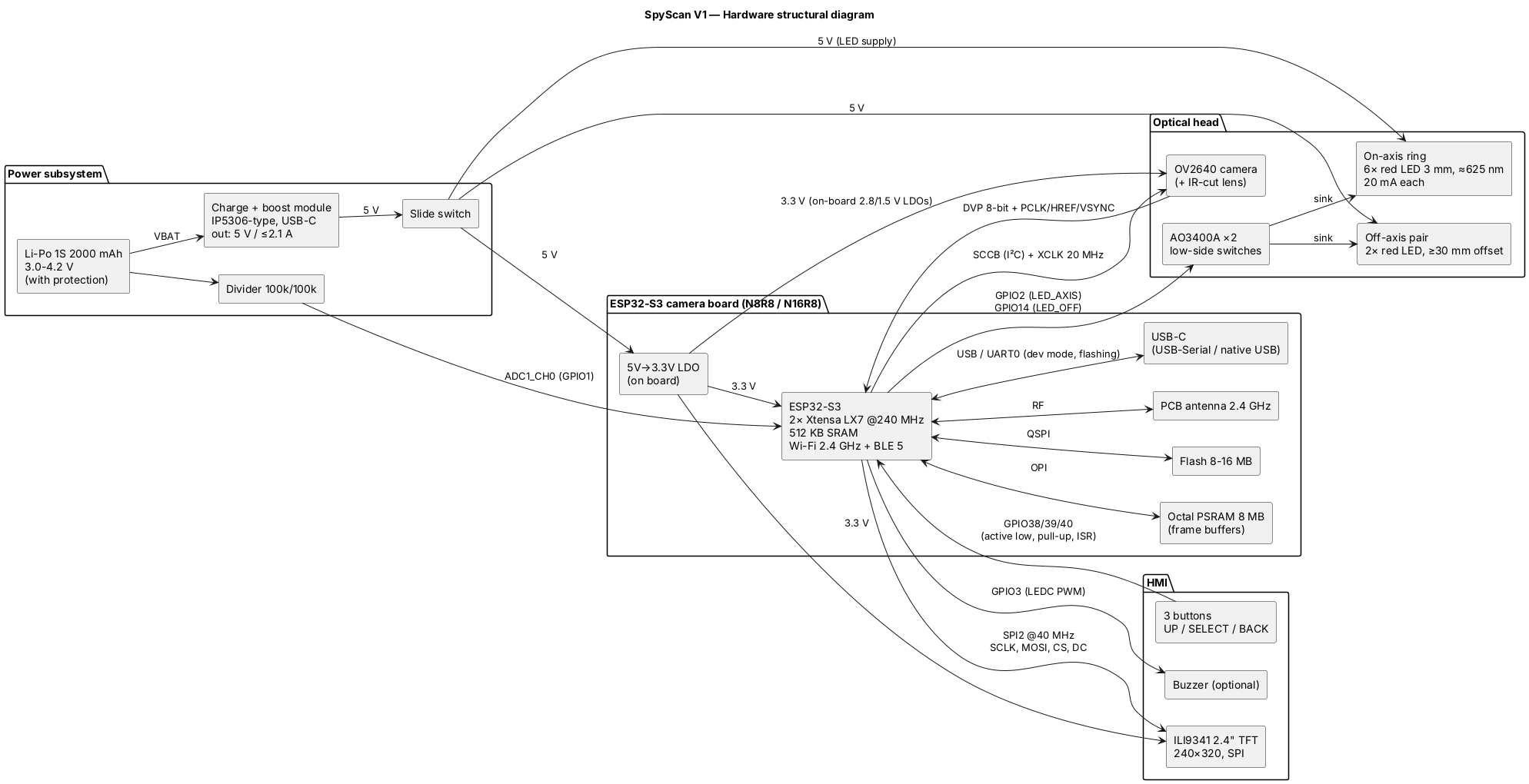
| Part | State |
|---|---|
| Technical specification v2 (revised after the defended draft) | Done |
| Hardware and software architecture, pin map, power budget, RTOS task design | Draft 0.1 |
| Wokwi simulation running the real UI state machine and challenge code | Done |
| PC unit tests: 22 UI transitions, Monte-Carlo test of the detector | Passing |
| Wi-Fi sniffer firmware (ESP-IDF, USB Serial/JTAG output) | Running on hardware |
| Python capture and analysis tools, permutation test, plots | Done |
| Passive streaming signature, packet-size shape, frame-clock analysis | Measured on two cameras |
| Optical bring-up firmware: live preview, LED on/off difference mode | Written, hardware test next |
| Optical head and enclosure | Next |
Decisions that changed the design
A brightness threshold is not a lens detector. The first draft looked for bright spots. That cannot reject lamps, indicator LEDs or reflections, so it was replaced with differential on/off imaging plus the off-axis test.
A network list does not show cameras. The first draft listed access points and Bluetooth devices. A camera connected as a client never appears in an access-point scan, so it was replaced with passive traffic monitoring and stimulus correlation, following published work (DeWiCam, Lumos).
The simulation added a third: a phone watching the camera's stream also follows the stimulus. The detector now checks direction, because the camera is the one sending video up, not receiving it.
The optical method became the primary detector. Real cameras showed that Wi-Fi only sees a camera while someone is watching it live. Light reflected from a lens does not depend on the camera transmitting, so the optical scan leads and Wi-Fi confirms.
Some methods are excluded on principle. Forcing a camera off the network to see how it reconnects would work, but it is a denial-of-service attack and illegal to transmit. SpyScan stays passive.
Results so far, including what did not work
The ESP32-S3 can watch a real room. The first run in a crowded dorm saw 28 access points and 18 active devices with no dropped frames and about 190 KB of memory to spare.
The stimulus test failed on real cameras, and that changed the design. I tested two mini Wi-Fi spy cameras with motion, light, covering the lens and a null control. Neither followed the pattern (p from 0.32 to 0.86; one light run reached 0.04 but was invalid, because the camera switched to night mode halfway). They stream at a constant bit rate whatever they see. Both also stop streaming when nobody is watching. The challenge stays for cameras whose encoders do react, but it cannot be the main detector.
The passive signature works. A camera streaming video looks different from everything else on the network: almost all its traffic goes up, it never pauses, and 83% of its packets are full-size video fragments. The rule flagged a camera in 9 of 9 runs where one was being watched, with no false flags on the router, the viewing phone or a laptop on a video call. Collapsing packets into frames also reveals the encoder's clock: one camera sends a frame every 40 ms, exactly 25 frames per second, which a person browsing or downloading never does.
The thresholds were tuned on the same runs they were tested on, so they still need validation on new data with harder distractors: cloud uploads, video calls and other smart-home devices.
Every claim is labelled
The repository follows one rule: each statement is marked as fact, assumption, hypothesis, decision, target or measured, and nothing is reported as a result unless the raw data and the script that produced it are committed next to it. Raw captures are never edited by hand. The tags on this page follow the same rule.
The device will also never claim to find every camera. A camera that is switched off, shielded or hidden behind a pinhole can defeat several methods at once, and the project documents those limits instead of hiding them.
Next
- Optical bring-up on the new board: first live test of the lens difference image.
- E1: measure the optical signal against distance, LED offset and ambient light.
- E2: validate the passive signature on fresh runs with distractors, and try the challenge on an ESP32-CAM, whose encoder should react to the scene.
- E3: test whether the on-axis/off-axis ratio separates lenses from shiny objects.
- E4: run the camera and the Wi-Fi monitor on one chip and measure frame loss, CPU and memory.
Latest from the lab
- Frame-clock fingerprint CONFIRMED (25 fps); focus capture fixed
Method 1.2 works, with a correction to my earlier skepticism. Raw per-packet inter-arrival is dominated by <2 ms within-burst gaps (one encoded frame = a burst of fragments). After collapsing packets into bursts (gap > 8 ms), the inter-burst interval peaks…
Closed-app run (03:49): camera dropped to 0.5 kB/s / 80 frames. It did not stand out in the keep-alive table this time (other APs/devices were more regular over 60 s); camera 2's keep-alive is less periodic than camera 1's 15 s beat. Keep-alive detection…
- New firmware verified: packet-size feature works; focus-capture bug found & fixed
Reflashed sniffer. 60 s record with camera 2 (cc:b8:…) streaming (camera 1 idle this session).
Packet-size shape (1.3) — strong measured result: the camera's uplink is 83 % max-size (≥1200 B) packets; every non-camera client was 100 % tiny (phone 72:3b, idle b2:db), and the AP relay was mostly mid-size. Clean separation. Refined the rule to…
- Wi-Fi method expanded to a feature set; taxonomy recorded
Reviewed a full taxonomy of Wi-Fi/RF detection methods (see docs/analysis/wifi_methods_taxonomy.md). Decided what to implement vs defer vs exclude, grounded in our E2 measurements. No new hardware needed for any of it.
Implemented now (all passive, ESP32-S3):
- Second spy camera (camera 2) on the same network
Run 01:13, camera 2 app open: camera 2 = cc:b8:5e:ad:5c:4a. It has a globally unique (non-random) MAC, unlike camera 1. Uplink 196 kB/s (≈ 1.6 Mbit/s), downlink 7.7, RSSI −46.
Run 01:16, camera 2 app closed: camera 2 at 0.38 kB/s (76 frames). It also streams only when watched, the same as camera 1.